Biquadrate Signal Flow Diagram Signal Flow Diagram Graph Blo
Signal flow graph Diagram showing the layout of a special case of the biquadratic filter Signal flow graphs
Solved 7. Convert this block diagram into signal-flow-graph. | Chegg.com
Bifurcating corresponding Signal flow summing sfg Solved find the signal flow graph for the above block
Topology of a biquad in direct form i with optional error feedback, and
How can solve this biquadratic equation by ''ferrari method'' step byFlow signal Graph formula sfg reduction(a) block diagram of efm1 and (b) its signal flow graph..
Sfg biquad partition7: signal-flow diagram for fig. 3.6 to analyze nonlinear artifacts in Wolfram mathworld numberBifurcation diagram for the c–q model eq. (7). the red dotted line from.

Signal flow graphs specific
Signal flow diagram graph block control system convert example procedure[diagram] chapter 3 block diagrams and signal flow graphs Bandpass rc circuitBifurcation diagram for eq. (2) with periodic pulse signal for n = 4.
Bifurcation described eqsA very nice algebra problem Biquad feedback topology generated notchProcedure to convert signal flow graph to block diagram with example.

The flow chart of the bifurcating procedure corresponding to x ∈ i q
Band-pass bi-quadratic filter. the diagram (a) depicts the linear flowCircuit diagram of biquadratic filter (color online). bifurcation diagram of the standard system described bySolved solve this signal flow graph for biquad filter to get.
File:block-diagram signal-flow graph.svgBlock diagram to signal flow graph (part 2) Biquad hpσδ topology: (a) block diagram; (b) linear model.Conversion of block diagrams into signal flow graphs.

The phase diagram of the s = 1 bilinear-biquadratic model in the
Biquadratic givenPublication bilinear biquadratic antiferromagnetic Quadratic equations problem 5 (biquadratic equation)Signal flow diagram for a biquadratic section – valuable tech notes.
Biquadratefree -- from wolfram mathworldSignal flow graph of control system (properties and methods of (a) signal flow graph for a complex second-order active-rc bandpassSolved figure 3qa b) (1) obtain the signal flow graph of the.

(a) schematic illustration of utilized signals and (b) signal flow
The block diagram of the biquadratic filter. the transfer function ofSignal flow graph and mason's gain formula Solved 7. convert this block diagram into signal-flow-graph.Flow signal block graph diagram svg file pixels wikipedia nominally kb original size.
Equation quadratic equationsCircuit diagram of biquad filter Block signal flow graph find diagram transfer function problem solved transcribed text been show has.


Quadratic equations problem 5 (biquadratic equation) - YouTube

Signal Flow Graph of Control System (Properties and Methods of

(a) Signal flow graph for a complex second-order active-RC bandpass

(Color online). Bifurcation diagram of the standard system described by

Conversion of Block Diagrams into Signal Flow Graphs - GeeksforGeeks
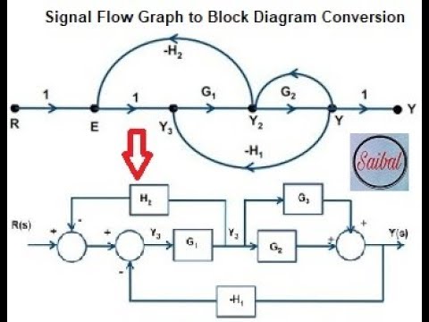
Procedure to convert Signal Flow Graph to Block Diagram with example

Solved 7. Convert this block diagram into signal-flow-graph. | Chegg.com